Few things are as frustrating as an electrical problem in your vehicle. A flickering dash light, a window that won't roll down, or worse, an engine that refuses to start – these issues often boil down to a hiccup in the complex web of wires and components that make up your car's electrical systems. This is where mastering Key Automotive System Wire Diagrams (e.g., Engine, Lighting, HVAC) becomes not just a skill, but a superpower.
These diagrams aren't just squiggly lines; they're the detailed blueprints that reveal how every electron flows through your car's critical systems, from ignition and charging to sophisticated engine controls and cabin comfort features. They're your personal roadmap to understanding, diagnosing, and ultimately fixing electrical faults, saving you time, money, and a fair bit of head-scratching.
At a Glance: Key Takeaways for Decoding Your Car's Electrical Heart
- Wiring diagrams are simplified maps: They show electrical connections and current flow, not physical wire placement.
- Essential for diagnosis: You can't effectively troubleshoot an electrical issue without understanding the circuit.
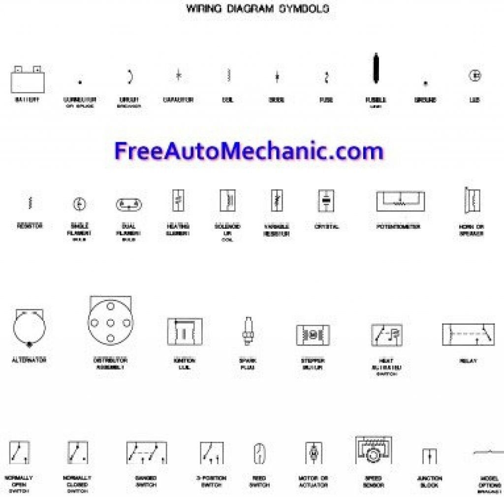
- Learn common symbols: Standardized icons represent components like batteries, switches, relays, and motors.
- Follow the current's path: Always trace from the power source (battery) through components to the ground connection.
- Wire colors matter: Use the diagram's legend to identify wire functions, as colors aren't universal.
- Safety first: Always disconnect the battery before working on electrical systems.
What Exactly Are Automotive Wiring Diagrams? Your Vehicle's Electrical Blueprint
Imagine trying to navigate a bustling city without a map, just by looking at buildings. That's essentially what you're doing when you try to diagnose a car's electrical problem without its wiring diagram. An automotive wiring diagram is a specialized, simplified drawing that illustrates the electrical connections between components within a vehicle. It uses standardized symbols for devices—like batteries, fuses, switches, relays, sensors, and motors—and lines to represent the wires that connect them.
Unlike a photo or a physical layout, these diagrams aren't concerned with the exact physical routing of wires under the hood or behind the dash. Instead, their primary purpose is to show you how electricity flows through a circuit and how each component interacts. Think of it as a logical flow chart for electrons, revealing the system's operational design. This focus on electrical connectivity rather than physical location makes them indispensable.
Why You Can't Afford to Ignore Them: The Crucial Role of Diagrams
For anyone tackling automotive repairs, whether a seasoned technician or a confident DIYer, wiring diagrams are an invaluable tool. Here's why they're non-negotiable for serious troubleshooting:
- Precision Troubleshooting: When a headlight won't turn on, is it the bulb, the fuse, the switch, or a faulty ground? A diagram allows you to methodically trace the circuit, isolating the exact point of failure. Without it, you're just guessing.
- Safe and Correct Installations: Adding aftermarket accessories, from a new stereo to auxiliary lighting, requires understanding existing circuits. Diagrams guide you to the correct power, ground, and signal wires, preventing dangerous short circuits, overloads, or damage to sensitive vehicle electronics.
- Preventing Electrical Hazards: Overloading a circuit, using incorrect wire gauges, or making poor connections can lead to electrical fires or component damage. Diagrams help you ensure your work respects the vehicle's original electrical design and safety parameters.
- Deeper System Understanding: They lay bare the intricate dance between different components. You'll grasp how the ignition system interacts with the charging system, or how multiple sensors feed data to the Engine Control Unit (ECU) to manage fuel injection. This knowledge empowers you beyond simple repairs. If you're looking to dive deeper into the world of vehicle electronics, you'll find an abundance of resources to learn about wire diagrams and their applications across various industries.
The Vehicle's Nervous System: Common Automotive Electrical Systems You'll Diagram
Modern vehicles are veritable supercomputers on wheels, packed with interconnected electrical systems. While the complexity can seem daunting, wiring diagrams break these down into manageable circuits. Here are some of the most common systems you'll encounter:
- Ignition System: This is what gets your engine running. Diagrams here show the battery, ignition switch, starter relay, and starter motor, detailing how current flows to crank the engine.
- Charging System: Once the engine is on, this system keeps your battery topped up. You'll see the alternator (generating power), the voltage regulator (controlling output), and the battery itself, ensuring a steady supply of electricity.
- Lighting System: From crucial safety features like headlights and brake lights to turn indicators and interior illumination, these diagrams show the switches, relays, fuses, and bulbs that light your way and communicate with other drivers.
- Fuel and Engine Control: This is the brainpower of your engine. Diagrams here will reveal the intricate connections between various sensors (oxygen, crankshaft position, mass airflow), fuel injectors, and the vehicle's ECU. These systems are highly integrated, with signals constantly communicating to optimize performance and efficiency.
- Comfort and Accessories: Think power windows, air conditioning, wipers, heated seats, and infotainment systems. These diagrams illustrate how switches, motors, control modules, and other components work together to enhance your driving experience.
It's vital to remember that these systems often don't operate in isolation. For instance, the ignition system directly influences the charging system, and engine control units often manage climate control or integrate with lighting for features like automatic headlights.
Your Blueprint for Troubleshooting: How to Read a Wiring Diagram, Step-by-Step
Reading a wiring diagram is a skill, and like any skill, it improves with practice. Here’s a methodical approach to deciphering these essential guides:
- Identify the Power Source: Every electrical circuit needs power, and in a car, that usually starts with the battery. Look for the standard battery symbol (a long line and a short line, typically with positive and negative terminals indicated). Some diagrams might also show the alternator as a primary power source when the engine is running. Your journey through the circuit always begins here.
- Trace the Ground Connection: Just as current needs a source, it also needs a return path, which is typically "ground." In automotive terms, the vehicle's metal chassis acts as the common ground. Look for the ground symbol, which often resembles descending parallel lines of decreasing length or a triangle pointing downwards. A significant number of electrical problems stem from poor ground connections, so always pay close attention to this return path.
- Locate Switches and Relays: These are the gatekeepers of current flow:
- Switches: These are manually or automatically operated devices that open or close a circuit to control a component. They can be simple on/off toggles or multi-position selectors.
- Relays: Relays are electrically operated switches. They allow a low-current control signal (e.g., from a headlight switch) to activate a higher-current circuit (e.g., to power the headlights). This protects the control switch from high electrical loads and allows for more efficient power distribution.
- Follow the Flow of Current: This is the core of diagram interpretation. Electricity generally flows from the positive (+) terminal of the battery, through protective devices (like fuses or circuit breakers), through switches or relays, into the "load" (the component doing the work, like a motor, light bulb, or sensor), and finally back to ground. By methodically tracing this path, you can pinpoint exactly where the circuit is interrupted or failing.
- Understand Wire Colors and Labels: Diagrams are often color-coded to match the physical wires in your vehicle. For example, a diagram might show "Red – Power," "Black – Ground," or "Yellow/Green – Signal." This is incredibly helpful for physically locating and testing wires. However, always, always consult the diagram's specific legend or key. Wire color codes are not universal and vary significantly between manufacturers and even models. What’s red on one car might be blue on another. The legend is your Rosetta Stone for that particular diagram.
A Practical Walkthrough: Deciphering a Headlight Circuit
Let's apply these steps to a common example: a basic headlight circuit.
Imagine your headlights aren't working. You pull out the diagram, and here's what you'd typically see and how you'd interpret it:
- Battery: Your starting point. Power originates here.
- Fuse: The first stop for current from the battery. This critical component protects the circuit from overcurrent. If the fuse is blown, the circuit breaks, and the headlight won't work. This is always one of the first things to check.
- Headlight Switch: This is the driver's control. When you flip the switch, it sends a low-current signal.
- Relay: The low-current signal from the switch activates the relay. The relay then closes a separate, higher-current circuit directly from the battery (or a fused power source) to the headlight bulb. This prevents the delicate headlight switch from having to handle the heavy current load of the headlights, prolonging its life.
- Bulb (Load): This is the component that uses the electricity to produce light. It's the "work" being done by the circuit.
- Ground Connection: After passing through the bulb, the current returns to the battery via the vehicle's chassis, completing the circuit.
In action: When you turn on your headlights, current flows from the battery, through the appropriate fuse, to the headlight switch. The switch then sends a low-current signal to activate the headlight relay. The relay, in turn, draws a heavy current directly from a fused battery source, sending it to the headlight bulb. The current then passes through the bulb, illuminates it, and returns safely to ground, completing the circuit. If any part of this chain is broken—a blown fuse, a faulty switch, a damaged relay, a bad bulb, or a corroded ground—the headlights won't work.
Beyond the Basics: Tips for Sharpening Your Diagram Interpretation Skills
Becoming proficient with wiring diagrams isn't just about knowing the symbols; it's about developing a strategic approach:
- Start Simple and Isolate: Don't try to understand the entire vehicle at once. Focus on one specific system or even a sub-circuit (like just the low beams). Isolate the relevant part of the diagram and ignore everything else initially. This reduces mental clutter.
- Leverage Wire Color Codes (with Caution): Once you've identified the power path and components on the diagram, use the indicated wire colors to physically locate and confirm wires in the vehicle. But remember, always double-check against the legend for that specific diagram.
- Fuses First, Always: When troubleshooting a dead circuit, always check the fuse first. It's the simplest and most common point of failure. The diagram will show you precisely which fuse protects which circuit.
- Use Your Multimeter: A diagram tells you where current should flow, but a multimeter tells you where it is flowing. Use it to check for voltage, continuity, and resistance at various points in the circuit as guided by the diagram. This validates your interpretation of the diagram against the vehicle's reality.
- Compare Diagram to Physical Components: Don't just stare at the paper. Look at the actual components in the vehicle. How many wires go into the switch? Do they match the diagram? This helps you orient yourself and verify the diagram's accuracy relative to your specific vehicle's configuration.
- Look for Connectors: Diagrams often show connectors (plugs, harnesses) with pin numbers. These are critical for segmenting circuits and testing individual wires within a bundle. They are also common points of failure due to corrosion or damage.
- Understand Component Locations: Some diagrams include general location information (e.g., "Fuse Box under hood," "Relay behind glove box"). This saves you precious time searching for components.
Common Pitfalls and How to Steer Clear
Even experienced technicians can make mistakes if they're not careful. Avoid these common blunders:
- Confusing Schematic Diagrams with Wiring Diagrams: While related, they serve different purposes. Schematics (or functional diagrams) often show the logical function of a circuit without necessarily representing the physical connections precisely. Wiring diagrams, on the other hand, focus on the physical connections and wire routing necessary for practical repairs. Always ensure you're using a true wiring diagram for troubleshooting.
- Ignoring Ground Connections: A surprising number of electrical issues, from dim lights to non-functional components, are caused by poor or corroded ground connections. Always trace the ground path on the diagram and physically inspect those points in the vehicle.
- Assuming Universal Color Codes: This is a trap! As mentioned, wire colors are not standardized across manufacturers. What's power on a Ford might be a signal wire on a Honda. Your vehicle's specific service manual and diagram legend are your only reliable sources.
- Skipping Safety Steps: Before touching any automotive wiring, always disconnect the battery's negative terminal. This prevents accidental shorts, electrical shocks, and damage to sensitive electronic components. Electrical work can be dangerous, so prioritize safety above all else.
- Not Understanding Relay Operation: Relays can be tricky. Many new troubleshooters incorrectly test the control side (low current) instead of the power side (high current) of a relay, or vice-versa. Understand the diagram's depiction of the coil (control circuit) and the contacts (power circuit).
- Overlooking Voltage Drop: A wire might have continuity, but if it's too thin or damaged, it can cause "voltage drop," meaning the component isn't getting enough voltage to operate correctly. Diagrams often specify wire gauges, which can be a clue.
Tools of the Trade: Equipping Your Electrical Workshop
To effectively use your wiring diagrams, you'll need a few essential tools:
- Vehicle Service Manual (or online subscription): This is your primary source for accurate wiring diagrams. Aftermarket manuals can be helpful, but factory service manuals are usually the most detailed and trustworthy.
- Digital Multimeter (DMM): An absolute must-have. You'll use it to measure voltage, resistance (ohms), and continuity. A good DMM helps you verify what the diagram suggests should be happening.
- Test Light: A simple, inexpensive tool that quickly indicates the presence of voltage. Great for quick checks, but a DMM offers more precise readings.
- Wire Strippers/Crimpers: For making clean, secure connections when repairs are needed.
- Heat Gun and Heat Shrink Tubing: For insulating and protecting repaired connections from moisture and abrasion.
- Assorted Connectors and Terminals: To replace damaged ones, ensuring robust electrical pathways.
- Terminal Removal Tools: To safely extract wires from connectors without damage.
- Safety Glasses and Gloves: Always protect your eyes and hands when working on any vehicle system.
Empowering Your DIY Journey: From Diagram to Diagnosis
Mastering automotive wiring diagrams is an invaluable skill that transforms you from a bewildered guesser into a confident problem-solver. It's the difference between blindly replacing parts and precisely diagnosing a fault. Every successful repair you perform using a diagram builds your confidence and deepens your understanding of how your vehicle truly works.
Start small, practice regularly with known good circuits, and always prioritize safety. The more you use these diagrams, the more intuitive they'll become. Soon, you'll be tracing complex circuits with ease, saving significant time, reducing frustrating guesswork, and ensuring safe, reliable electrical work on your vehicle. So, grab your service manual, a multimeter, and embark on your journey to becoming an automotive electrical detective.