Imagine trying to navigate a complex city without a map, or assembling intricate furniture without instructions. That's what diagnosing modern vehicle electrical issues feels like without Understanding Automotive Wire Diagrams. These aren't just squiggly lines on a page; they're the essential blueprints of your vehicle's nervous system, translating complex wiring harnesses into a simplified, visual language. Mastering them is arguably the most critical skill for anyone serious about accurate and efficient automotive electrical repair.
It's the difference between guessing and knowing, between swapping parts endlessly and pinpointing a fault with precision. When you understand how to read these diagrams, you gain the power to trace electrical energy flow, identify components, and diagnose problems with a systematic approach that saves time, money, and frustration.
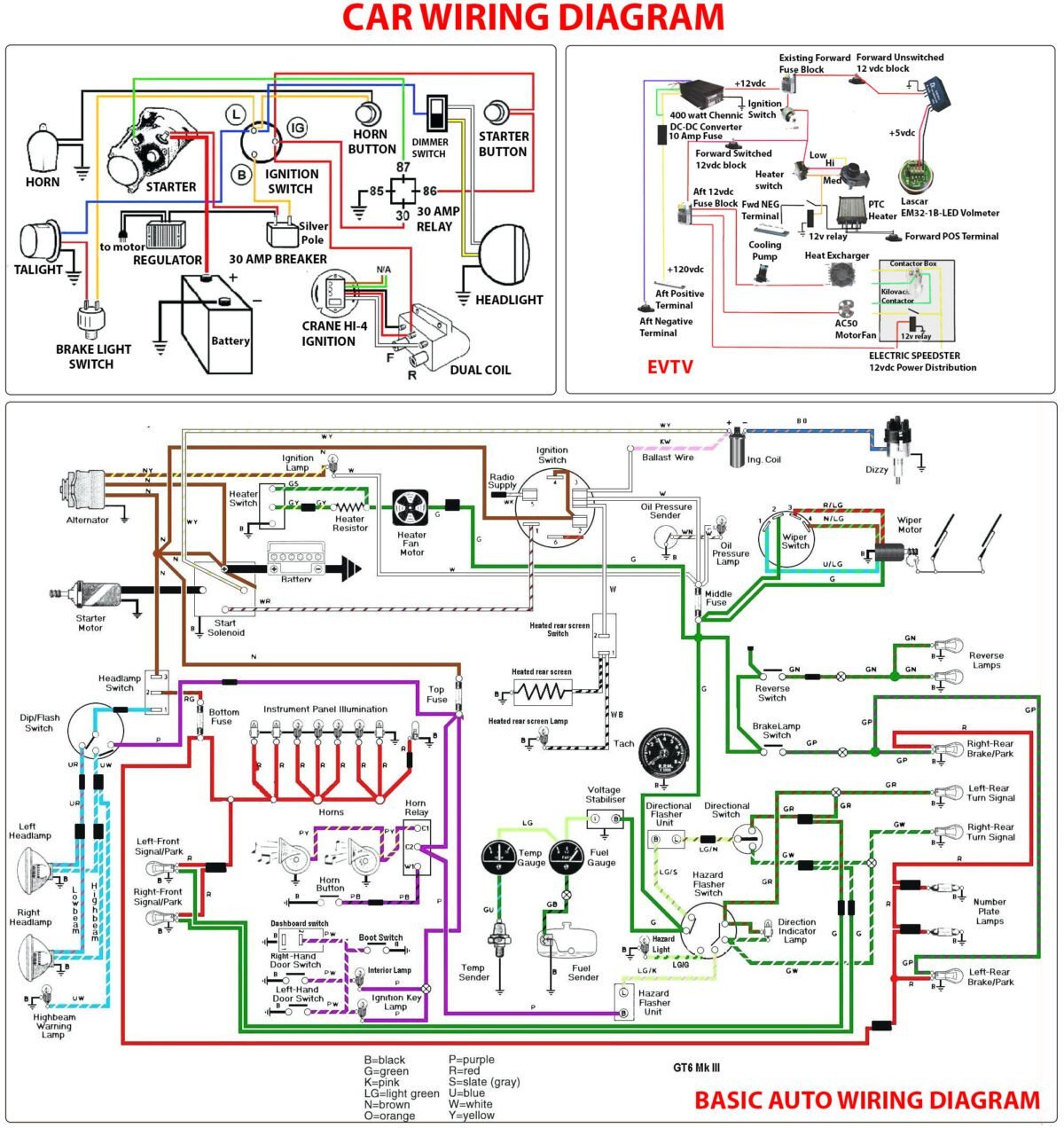
At a Glance: Your Roadmap to Reading Automotive Wire Diagrams
- Learn the Language: Diagrams use a universal set of symbols for wires, connections, grounds, batteries, fuses, relays, and more. Memorizing these is step one.
- Follow the Power: Electrical current typically flows from the power source (top) to the ground (bottom) on a diagram.
- Identify Components: Each switch, sensor, and motor has an alphanumeric code (e.g., "C205") and terminal numbers to help you find it on the actual vehicle.
- Understand Wire Codes: Wires are identified by color (e.g., "LT BLU/YEL" for Light Blue with a Yellow stripe) to match the diagram to the physical harness.
- Trace the Circuit: Use the diagram to follow the path of electricity, identify where it loses power (open circuit), or where it's shorting to ground.
- Diagnose Systematically: Diagrams guide your multimeter testing, helping you check voltage, resistance, and continuity at precise points.
Why Wire Diagrams Are Your Best Friend in the Garage
Modern vehicles are essentially computers on wheels, packed with sensors, modules, and intricate electrical networks. Gone are the days of purely mechanical troubleshooting. Today, a significant percentage of vehicle malfunctions stem from electrical issues – anything from a dead headlight to a mysterious engine misfire.
Without a wiring diagram, you're essentially blind. You can't see the intended path of current, how components are connected, or where a fault might interrupt that flow. A diagram provides that critical visibility, allowing you to:
- Pinpoint Failures: Quickly identify the exact component or wire segment responsible for a problem.
- Avoid Guesswork: Stop replacing parts "just in case" and make data-driven repairs.
- Save Time and Money: Efficient diagnosis means fewer hours spent laboring and less wasted money on unnecessary parts.
- Understand System Logic: Grasp how different electrical systems interact and depend on each other.
Think of it this way: the wiring diagram isn't just a guide for repair; it's a guide for understanding. And understanding is the bedrock of effective troubleshooting.
The Blueprint Language: Deciphering Automotive Symbols
At its heart, reading an automotive wire diagram is like learning a new language – a consistent, structured language of graphical symbols. Once you know these fundamental building blocks, entire circuits begin to make sense.
Let's break down the most common symbols you'll encounter:
Wires and Connections: The Arteries of the System
- Wire: Represented by a simple straight line. This is the path electrical current takes. Lines often have labels next to them indicating wire color, gauge, and sometimes a circuit number.
- Electrical Connection/Splice: A solid dot where lines intersect indicates that the wires are electrically connected. Current can flow from one wire to the other at this point.
- Unconnected Crossing Wires: If lines cross without a dot, it means the wires are not connected and simply pass over or under each other. This is a crucial distinction to avoid misinterpreting a circuit.
Power and Ground: The Start and End Points
- Battery: Shown as alternating long and short parallel lines. The longer line represents the positive (+) terminal, and the shorter line represents the negative (-) terminal. This is the primary power source for the entire vehicle.
- Ground: A rake-like symbol (a downward line ending in progressively shorter horizontal lines) signifies a connection to the vehicle's chassis or engine block. This is the return path for electrical current, completing the circuit. A solid, reliable ground is essential for any electrical component to function.
Circuit Protection: Fuses and Circuit Breakers
- Fuses: Typically represented by a short wavy line or a rectangular box. Fuses are intentionally designed weak points in a circuit. They sacrifice themselves by melting and breaking the circuit if too much current flows, protecting more expensive components from damage. Understanding which fuse protects which circuit is vital when diagnosing a "dead" component.
- Circuit Breakers: Often a rectangular box with a "thermal" or "magnetic" indicator. Like fuses, they protect circuits, but unlike fuses, they can be reset (either automatically or manually) after tripping.
Resistors and Capacitors: Controlling the Flow
- Resistors: Depicted as a zigzag line. Resistors impede the flow of electrical current, reducing voltage and current to specific components, like dimming a light or controlling a motor's speed.
- Capacitor: Two parallel vertical lines with a small gap between them (often with one line being slightly curved or having a plus sign for polarized capacitors). Capacitors store electrical charge and can smooth out voltage fluctuations or filter signals.
Relays and Switches: The Decision-Makers
- Relay: A box containing a coil symbol and contacts. Relays are electro-mechanical switches. A small amount of current in the coil circuit creates a magnetic field that pulls contacts together, allowing a much larger current to flow through a separate load circuit. This is incredibly common in vehicles, separating low-current control signals from high-current loads (e.g., a tiny switch activating a powerful starter motor).
- Coil: Typically a small rectangle or a series of loops.
- Contacts: Shown as a movable break in the line.
- Normally Open (NO): Contacts are apart when the coil is de-energized, closing when energized.
- Normally Closed (NC): Contacts are together when the coil is de-energized, opening when energized.
- Switches: A movable break in the line, with various configurations.
- Single Pole, Single Throw (SPST): A simple on/off switch.
- Single Pole, Double Throw (SPDT): Switches current between two different paths (e.g., high beam/low beam).
- Multi-pole/Multi-throw: More complex switches controlling multiple circuits or paths.
- Switches can be momentary, maintained, push-button, rocker, etc. The symbol often indicates its physical actuation.
Other Common Symbols
- Lamp/Light Bulb: A circle with a cross inside.
- Motor: A circle with an "M" inside.
- Diode: A triangle pointing in the direction of current flow with a bar at its tip, allowing current to flow in only one direction.
- Sensor: Often a rectangle or oval with specific internal symbols or letters indicating its function (e.g., "TPS" for Throttle Position Sensor).
- Electronic Control Unit (ECU)/Module: A large rectangle representing the computer that controls various systems. It will have numerous inputs and outputs.
By recognizing these symbols, you're not just seeing lines; you're seeing components and their intended functions, laying the groundwork for truly understanding the intricacies of wire diagrams.
Navigating the Layout: Where Does Everything Go?
Symbols are the alphabet, but the layout is the grammar. Automotive wire diagrams follow a consistent structure to make them readable, even across different manufacturers.
Power Flow: Top to Bottom, Left to Right
Most diagrams are designed to reflect the natural flow of electrical power.
- Top: Typically where the power source originates – often a fuse block, the battery itself, or a main power distribution point. Wires carry positive (+) voltage from these points.
- Middle: This is where the bulk of the circuit lies, containing components like switches, relays, motors, and control modules.
- Bottom: Generally where the circuit terminates at a ground connection, completing the path back to the battery's negative terminal.
While this top-to-bottom flow is common for individual circuits, overall diagrams might organize systems side-by-side or by logical blocks.
System Organization: Grouping Related Circuits
Complex vehicles can have hundreds of circuits. To manage this, diagrams are often organized by system. You'll find separate pages or sections for:
- Engine Management (fuel injection, ignition)
- Lighting (headlights, tail lights, interior lights)
- Brakes (ABS, traction control)
- Body Electrical (power windows, locks, mirrors)
- Climate Control (HVAC)
- Infotainment (radio, navigation)
This organization helps you quickly find the relevant section for the issue you're diagnosing. For example, if a headlight isn't working, you'd turn to the "Lighting" section rather than sifting through engine diagrams.
Component and Connector Identification: Finding It on the Car
This is where the diagram truly bridges the gap between the paper and the physical vehicle.
- Component Codes: Each major component (e.g., a motor, sensor, or module) will have an alphanumeric code (e.g., 'ECM' for Engine Control Module, 'FP' for Fuel Pump).
- Connector Codes: Connectors, which join different parts of the wiring harness, are critical. They typically have a code like 'C205' or 'X101'.
- The letter (e.g., 'C' or 'X') often indicates a general vehicle area (e.g., C for "connector," X for "crossover" or "splice point").
- The number (e.g., '205') is a unique identifier within that area. A diagram might also include a small image or pinout view of the connector to help you identify it visually.
- Terminal Numbers: Within each connector or component, individual wires connect to specific terminals, which are always numbered. So, you might see "RED/BLK wire to terminal 3 of C104." This level of detail is invaluable for testing individual wires without disturbing the entire harness.
Continuation Lines: Tracing Across Pages
Automotive electrical systems are too complex for a single page. Circuits often span multiple pages. When a wire leaves one page to continue on another, you'll see a continuation line (often a dashed line or an arrow) with a label indicating:
- The sheet number where the circuit continues (e.g., "TO PAGE 12, GRID B4").
- A descriptive label for the circuit it connects to (e.g., "TO ECM PIN 42").
This allows you to seamlessly follow the electrical path, even through a multi-page comprehensive guide to wire diagrams.
Relays: Differentiating Control and Load Circuits
Relays are a common point of confusion. Remember, they have two distinct circuits:
- Control Circuit: This is the low-current side that energizes the relay's coil. It typically involves a switch, a power source, and a ground path. When the coil is energized, it creates a magnetic field.
- Load Circuit: This is the high-current side that is switched by the relay's contacts. It typically involves a separate power source (often fused directly from the battery), the contacts, and the component it powers (e.g., fuel pump, headlights).
Diagrams will often separate these two circuits visually within the relay symbol, or show them as distinct paths leading into and out of the relay, making it clear which wires power the coil and which wires carry the load.
The Nitty-Gritty: Wire Identification Codes
Beyond the symbols and layout, the wires themselves have a language you need to understand: the wire identification codes.
- Alphanumeric Labels: Wires are labeled with alphanumeric codes that typically indicate their main color and any stripe color.
- 'LT BLU/YEL' or 'LB/Y' means Light Blue with a Yellow stripe.
- 'RED' means a solid Red wire.
- 'BLK/WHT' means Black with a White stripe.
- Common abbreviations include: B (Black), BR (Brown), G (Green), GR (Gray), L (Blue), LG (Light Green), O (Orange), P (Pink), R (Red), V (Violet), W (White), Y (Yellow).
This labeling is critical because it allows you to physically locate the correct wire in a bundle, matching it precisely to the diagram. Without these color codes, locating a specific wire in a thick harness would be a nightmare. - Wire Gauge: Sometimes, diagrams will also specify the wire gauge (thickness), which is important for understanding current capacity. Thicker wires (smaller gauge numbers, e.g., 10-gauge) carry more current than thinner wires (larger gauge numbers, e.g., 20-gauge).
Matching the wire color and location to the diagram is often the first real step in bridging the gap between schematic and physical diagnosis.
Putting It All Together: Applying Diagrams to Real-World Diagnosis
Now for the practical part: how do you use all this knowledge to actually fix a car? This is where your ability to read the map translates into successful navigation.
The Multimeter as Your Translator
Your multimeter is the tool that reads the electrical signals the diagram predicts. The diagram tells you where to test, and the multimeter tells you what the values are.
- Voltage Checks: To see if power is getting to a component. Place the red lead at a point on the diagram where voltage should be present (e.g., the power input to a switch), and the black lead to a known good ground. The diagram shows the intended voltage (e.g., 12V).
- Resistance Checks (Continuity): To verify an unbroken path or a good ground. With the circuit de-energized, use the ohms function. The diagram helps you identify the start and end points of a wire segment or a component's internal resistance. A good wire should show very low resistance (close to 0 ohms). An open circuit will show "OL" (open loop/infinite resistance).
- Continuity to Ground: To test if a wire is accidentally shorted to ground. Place one lead on the wire in question and the other on a chassis ground. If you read near 0 ohms, that wire is shorted to ground.
Diagnosing a Blown Fuse: Finding the Short
A blown fuse is a symptom, not the problem. It means too much current flowed, usually due to a short circuit. The diagram is indispensable here.
- Identify the Fused Circuit: Locate the blown fuse on the diagram. It will show you exactly which components and wires are on that circuit.
- Isolate Sections: The diagram helps you see splices and connectors. You can often disconnect components or harness sections one by one.
- Trace to Ground: With the fuse removed, use your multimeter on the ohms setting. Place one lead into the load side of the fuse holder (the side that goes to the components) and the other lead to ground.
- Disconnect Systematically: If you read very low resistance (near 0 ohms), you have a short to ground. Start disconnecting components or harness connectors one at a time, retesting after each disconnection. When the resistance suddenly goes high ("OL"), you've just disconnected the section containing the short.
- Visually Inspect: Once the section is isolated, use the diagram's wire colors and routing information to physically trace the wires, looking for rubbed-through insulation, pinched wires, or corroded connections that could be causing the short.
Troubleshooting an Open Circuit: Where Did the Power Go?
An open circuit means the electrical path is broken, and current can't flow. A component simply doesn't receive power.
- Start at the Power Source: Begin at the battery or the fuse that powers the circuit. Verify voltage is present there.
- Follow the Diagram's Path: Systematically work your way along the circuit shown on the diagram, checking for voltage at each critical point:
- Fuse output: Is power leaving the fuse?
- Switch input/output: Is the switch passing power when activated?
- Relay contacts: Is the relay coil energizing, and are its contacts closing to pass power?
- Connector pins: Is power making it to and through connectors (e.g., C205)? Use the terminal numbers for precise testing.
- Component input: Is power actually reaching the component itself?
- Find the Break: When you find a point where voltage is present before it, but absent after it, you've located the open circuit. This could be a broken wire, a faulty switch, a corroded connection within a connector, or an internal component failure.
- Check Ground Last: Don't forget the ground! If power is reaching the component but it's not working, verify the component has a good, low-resistance path to ground using your multimeter's ohms setting.
Pinpointing a Short Circuit: Beyond the Fuse
Sometimes a short isn't severe enough to blow a fuse immediately, or it causes intermittent issues. The diagram helps here too:
- Identify the Affected Circuit: Determine which circuit is behaving abnormally.
- Measure Voltage Drop: While the circuit is operating (if possible), measure voltage drops across various points identified by the diagram. An unexpected voltage drop could indicate resistance due to a partial short or poor connection.
- Parasitic Draw: If the battery is draining, the diagram helps you identify circuits to test for parasitic draw. Disconnect fuses one by one, using an ammeter in series with the battery to see which circuit causes the draw to drop significantly. Then, use the diagram to delve into that specific circuit.
Component Failure: Verifying Inputs and Outputs
If a component isn't working, the diagram helps you verify its operating conditions:
- Power Input: Does the diagram show a constant 12V or switched 12V? Test for it.
- Ground Connection: Is a solid ground provided to the component as per the diagram? Test for continuity to ground.
- Signal Input (if applicable): If it's a sensor or module, does it receive the correct signal from another component? (e.g., a crank sensor signal to the ECM). The diagram will show these connections.
- Output (if applicable): Is the component sending out its expected signal or power? (e.g., an ECM sending a fuel injector pulse).
The diagram tells you exactly what to expect at each terminal and connection point. For more in-depth troubleshooting, you might refer to a detailed automotive wire diagram guide.
Connector and Terminal Checks: The Weak Links
Connectors are common failure points due to corrosion, loose pins, or physical damage.
- Diagram's Role: The diagram shows the connector's location, number, and pinout. It details which wire colors go to which terminal numbers.
- Physical Inspection: After identifying the connector from the diagram, visually inspect it for bent pins, corrosion, or pushed-out terminals.
- Terminal Tension: Carefully test individual terminals within the connector for proper tension using a small pick or appropriate terminal testing kit. A loose terminal can cause intermittent connection issues.
- Wiggle Test: While monitoring voltage or signal with your multimeter, gently wiggle wires and connectors. If the reading changes, you've found a likely intermittent fault.
Advanced Tips for Mastering Schematics
Even with the fundamentals down, a few advanced practices can elevate your diagnostic game.
Overlaying Multiple Diagrams
Often, a single system interacts with several others. For example, a vehicle's starting circuit involves:
- The ignition switch (body electrical)
- The starter relay (engine electrical)
- The battery (power distribution)
- The transmission range sensor (powertrain control)
You might need to reference diagrams from multiple sections or even different manuals to fully grasp a complex interaction. Learning to navigate efficiently between these linked systems is a mark of a truly skilled technician, providing a truly comprehensive understanding of automotive electrical systems.
Understanding Manufacturer Variations
While the core symbols are standardized, manufacturers have their own quirks:
- Layout Style: Some prefer very dense diagrams, others more spread out.
- Labeling Conventions: 'C' for connector is common, but some might use 'X' or 'J' (jumper).
- Wire Color Abbreviations: While standard abbreviations exist (B, R, W, Y, G, L, O, P, V), some manufacturers might use slightly different ones or add unique symbols for gauge or wire type.
- Ground Point Identification: Some diagrams detail specific ground points (e.g., "G101"), while others just use the general ground symbol.
Always consult the legend or introductory pages of the specific service manual you're using.
The Importance of Up-to-Date Diagrams
Vehicle designs evolve rapidly, often with minor changes mid-model year. Using an outdated diagram can lead to frustrating misdiagnoses. Always ensure you are using the most current wiring diagram for the exact year, make, model, and even trim level of the vehicle you are working on. Subscription services for factory service information are often the best source for this. You want to make sure you have the best possible resource for automotive wiring diagrams.
Common Mistakes and How to Avoid Them
Even seasoned pros can stumble if they're not careful.
- Ignoring the Legend: Don't assume you know every symbol. Always check the diagram's legend, especially for unfamiliar vehicles or complex systems. A new symbol could mean a completely different component.
- Jumping to Conclusions: Resist the urge to guess. Follow the diagram systematically. Don't assume a fuse blown means the component it powers is bad; it could be the wiring leading to it.
- Not Verifying Physical Connections: The diagram shows how things should be connected. Always visually inspect and physically test the actual wires and connectors on the vehicle. Corrosion, loose pins, or damaged insulation are incredibly common and won't show up on a diagram.
- Testing with Power On (When You Shouldn't): When checking resistance or continuity, the circuit must be de-energized. Otherwise, you risk damaging your multimeter or getting inaccurate readings. The only time to test with power is for voltage drops or current draw.
- Not Checking Both Sides of a Circuit: Always check for both power and ground. A component needs both to function. A common mistake is only checking for 12V and forgetting to verify a good ground path.
Frequently Asked Questions About Automotive Wire Diagrams
What are the basic symbols I need to know in a wiring diagram?
The most fundamental symbols include straight lines for wires, dots for connections, a rake-like symbol for ground, alternating long and short lines for the battery, zigzag lines for resistors, wavy lines or boxes for fuses, and a circle with an "M" for motors.
How do I read wire color codes in a diagram?
Wire codes are typically alphanumeric abbreviations. For example, "LT BLU/YEL" or "LB/Y" means a light blue wire with a yellow stripe. The first part is the main color, and the second is the stripe color. Always refer to the diagram's legend for specific abbreviations if unsure.
What's the difference between an open circuit and a short circuit?
An open circuit is a break in the electrical path, preventing current flow (like a broken wire or a blown fuse). A component won't receive power. A short circuit is an unintended path for current, usually to ground, which bypasses the intended load. This causes excessive current flow, often blowing a fuse or damaging components.
How do I use a wiring diagram to find a blown fuse's cause?
Identify the fuse on the diagram to see which components it protects. With the fuse removed, use an ohmmeter to check for continuity between the load side of the fuse holder and ground. If you read very low resistance, there's a short. Systematically disconnect components or harness sections shown on the diagram until the resistance goes high, indicating you've isolated the shorted section.
What do component codes like 'C205' or 'ECM' mean?
'C205' typically refers to a specific electrical connector (Connector 205). 'ECM' stands for Engine Control Module, the vehicle's primary computer. These alphanumeric codes help you locate specific parts and connections on the physical vehicle and refer to their detailed pinouts.
Why do some wires cross without a dot?
Wires crossing without a dot simply means they are passing over or under each other and are not electrically connected. A solid dot is always used to indicate an electrical connection or splice.
Equipping Yourself for Confident Automotive Electrical Repair
Mastering automotive wire diagrams is less about memorizing every single circuit and more about understanding the language and the systematic approach they enable. It's a skill that will empower you to tackle complex electrical issues with confidence, transforming frustrating guesswork into precise diagnosis.
Start small. Pick a simple circuit, like a headlight or a horn, and trace its path on a diagram. Identify the fuse, the switch, the relay, the component, and the ground. Then, physically locate those components in your vehicle. The more you practice, the more intuitive it becomes, turning an intimidating jumble of lines into a clear, actionable map. The journey to truly master all things automotive wire diagrams begins with that first step. Happy tracing!